Iranian Classification Society Rules

< Previous | Contents | Next >
Section 3 Engine Output
301. Definition of engine output
The engine output is the maximum output the propulsion machinery can continuously deliver to the propeller(s). If the output of the machinery is restricted by technical means or by any regu- lations applicable to the ship, shall be taken as the restricted output.
302. Required engine output for Ice classes IA Super, IA, IB, IC and ID
The engine output shall not be less than that determined by the formula below and in no case than 1000 kW for Ice class IA, IB, IC and ID, and not less than 2800 kW for IA Super.
1. Definitions
The dimensions of the ship and some other parameters are defined below:
less
= length of the ship between the perpendiculars (m)
= length of the bow (m)
= length of the parallel midship body (m)
= maximum breadth of the ship (m)
= actual Ice class draughts of the ship according to 202. 2 (m)
= area of the waterline of the bow (m 2)
= the angle of the waterline at B/4 (deg)
= degree
= degree
the rake of the stem at the centerline (deg) the rake of the bow at B/4 (deg)
= diameter of the propeller (m)
= thickness of the brash ice in mid channel (m)
= thickness of the brash ice layer displaced by the bow (m)
![]()
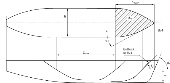
Fig 1.2 Determination of the geometric quantities of the hull. If the ship has a bulbous bow, then
= 90°.
2. New ships
To be entitled to Ice class IA Super, IA, IB, IC or ID a ship the keel of which is laid or which is at a similar stage of construction on or after 1 September 2003 is to comply with the following requirements regarding its engine output. The engine output requirement is to be calculated for two draughts. Draughts to be used are the maximum draught amidship referred to as UIWL and the minimum draught referred to as LIWL, as defined in 202. In the calculations the ship's parameters which depend on the draught are to be determined at the appropriate draught, but L and B are to be determined only at the UIWL. The engine output is not to be less than the greater of these two outputs.
[kW],
where : as given in Table 1.2
Table 1.2 Values of constant
Number of Propeller | CP or electric or hydraulic propulsion machinery | FP propeller |
1 propeller | 2.03 | 2.26 |
2 propellers | 1.44 | 1.60 |
3 propellers | 1.18 | 1.31 |
These values apply for conventional propulsion systems. Other methods may be used for de- termining the required power for advanced propulsion systems (see Par 5).
RCH is the resistance in Newton of the ship in a channel with brash ice and a consolidated sur- face layer:
![]()
where 0.45.
cos sin sin , is to be taken equal or larger than
= 1.0 for Ice class IA and IA Super
= 0.8 for Ice class IB
= 0.6 for Ice class IC
= 0.5 for Ice class ID
and = coefficients obtained by taking into account a consolidated brash ice
upper layer of the
For ships of Ice classes IA, IB, IC and ID : , For ships of Ice classes IA Super
For a ship with a bulbous bow, is to be taken as
and = values given in Table 1.3
Table 1.3 and
(N m ) | 23 | (N) | 1530 | (kg/(m s )) | 845 |
(N m ) | 45.8 | (N m ) | 170 | (kg/(m s )) | 42 |
(N m ) | 14.7 | (N m ) | 400 | (kg/s ) | 825 |
(N m ) | 29 |
= arctan
is not to be taken as less than 5 and not to be taken as more than 20.
Further information on the validity of the above formulas can be found in Annex I together with sample data for the verification of powering calculations. If the ship’s parameter values are beyond
the ranges defined in Table 1.1 of Annex I, other methods for determining defined in Par 5.
3. Existing ships of Ice class IB or IC
shall be used as
To be entitled to retain Ice class IB or IC a ship, the keel of which has been laid or which has been at a similar stage of construction before 1 September 2003, is to comply with the following requirements regarding its engine output. The engine output is not to be less than that determined by the formula below and in no case less than 740 kW.
![]()
· · ∆
where
bow
for a fixed pitch
for a controllable pitch propeller
but not more than 1.1 and 1.1 for a bulbous
where,
is the rake of the stem at the centerline [degrees] (see Fig 1.2) The product X shall not be taken as less than 0.85.
∆ but not less than 1.0
Table 1.4 Value or
Ice class | IB | IC | IB | IC |
Displacement | < 30000 | ≥ 30000 | ||
0.22 | 0.18 | 0.13 | 0.11 | |
370 | 0 | 3070 | 2100 | |
is displacement [t] of the ship on the maximum Ice class draught according to 202. 1.
It need not be taken as greater than 80,000 t.
4. Existing ships of Ice class IA Super or IA
To be entitled to retain Ice class IA Super or IA a ship, the keel of which has been laid or which has been at a similar stage of construction before 1 September 2003, shall comply with the re- quirements in Par 2 above at the following dates:
- 1 January 2005 or
- 1 January in the year when 20 years has elapsed since the year the ship was delivered, which- ever occurs the latest.
When, for an existing ship, values for some of the hull form parameters required for the calcu- lation method in section Par 2 are difficult to obtain, the following alternative formulae can be used:
Where,
For ships of Ice classes IA,
For ships of Ice classes IA Super without a bulbous bow, and is to be calculated as fol- lows;
![]()
For ships of Ice classes IA Super with a bulbous bow, and is to be calculated as follows;
and = values given in Table 1.5
Table 1.5 Values of and
(N m ) | 10.3 | (N) | 1530 | (kg/(m s )) | 460 |
(N m ) | 45.8 | (N m ) | 172 | (kg/(m s )) | 18.7 |
(N m ) | 2.94 | (N m ) | 400 | (kg/s ) | 825 |
(N m ) | 5.8 |
is not to be taken as less than 5 and not to be taken as more than 20.
5. Other methods of determining or
For an individual ship, in lieu of the or values defined in Par 2 and 3, the use of or values based on more exact calculations or values based on model tests may be approved.
Such an approval will be given on the understanding that it can be revoked if experience of the ship’s performance in practice motivates this.
The design requirement for Ice classes is a minimum speed of 5 knots in the following brash ice channels:
IA Super IA
IB
IC ID
= 1.0 m and a 0.1 m thick consolidated layer of ice
= 1.0 m
= 0.8 m
= 0.6 m
= 0.5 m